FasTrak Visor Holder
Explore how I designed and created the first ever FasTrak holder that clips onto your visor.
The Redesign
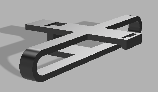
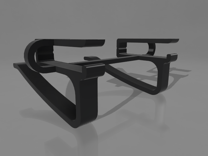
I wanted to keep my design simple to create while also remaining accessible. I added a curve to the bottom (shown as top) so it would be easy to put the FasTrak into the holder while the little nub on the right side would prevent the FasTrak from sliding out.
I also added side barriers that would keep the FasTrak in place preventing it from sliding out of the sides. This barrier is a perfect fit for the FasTrak Flex as it follows the radius of the device.
Along with these changes, I redesigned the clip portion of the holder (bottom), instead of having the clip rely on pure stiffness from the first design, the new design relies on flexibility. This helps the holder stay on the visor without sliding off easily.
This design is super easy to use especially with the addition of the triangular indent and circular indent on the left side that provide a designated spot for flexibility.
Current Progress & Thermal Limits
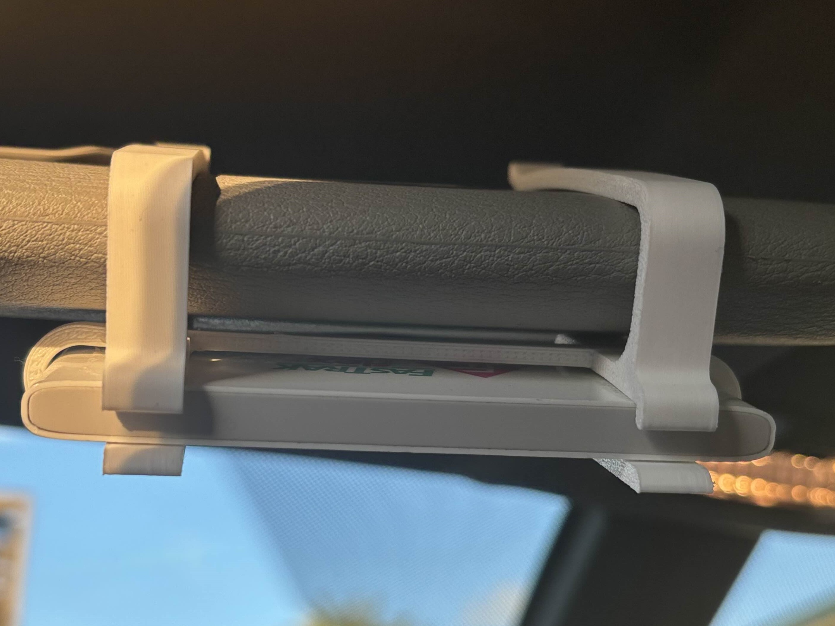
As of August 25, 2025; the FasTrak holder works as intended, it slides onto the visor in my vehicle and is easy to use. I am able to remove it when needed and easily place it back.
Unfortunately PLA is not great in warmer temperatures, so after about 1 day with 75 degree temperatures (close to 90 degrees in the vehicle) the plastic started to warp and deform due to the heat and pressure it has to withstand.
I am in the process of using a different material; HT-PLA-GF Filament by Polymaker. While this filament does require a new nozzle for my 3D Printer, it provides the reliability of being able to withstand higher temperatures and pressures due to the added glass fiber.
HT-PLA-GF Filament Integration
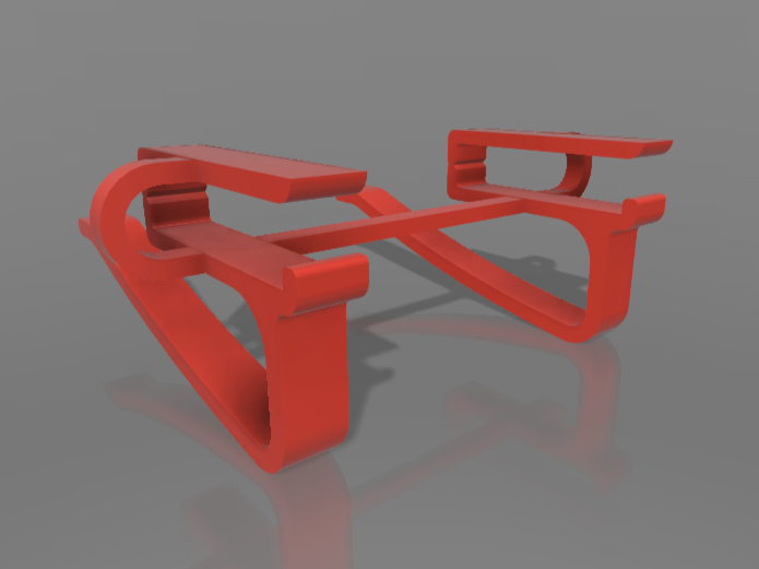
After receiving Black HT-PLA-GF produced by Polymaker as-well as a new Hardened Steel Nozzle for my printer; I started the process of printing out parts with the new material.
Initially I experienced a few difficulties with using the new material as it was a new experience. I’ve only ever worked with generic PLA from Sunlu, Bambu Labs, and a few other companies.
Compared to generic PLA, the HT-PLA-GF required a higher hot end temperature to effectively melt the plastic. This was an increase from around 190-200 degrees celsius to around 230 degrees at a minimum.
The Annealing Process
First, what exactly does it mean to Anneal PLA and why should it be done? Annealing is a heat treatment process that increases the strength in a material and heat-resistance by inducing crystallization.
You can think of it like a hair-dryer or iron; you need to heat up your hair which is currently frizzy and unmanageable. After you heat up your hair you can style it to your desired style and let it cool off. Your hair will typically remain the same throughout the day no matter how many times you mess with it.
Annealing should be done when your print is expected to withstand higher temperatures and stresses that standard non-annealed PLA can withstand.
Open-Air vs. Fine-Salt Annealing
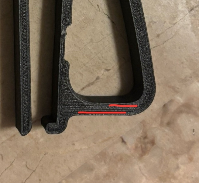
I chose two different annealing processes for this project: Open Air Annealing and Fine-Salt Annealing. Open Air Annealing consists of simply adding parts into an oven at 100 degrees celsius for 30 minutes. The main issues with this are that the parts are prone to warping and drooping if handled and placed incorrectly.
Fine-Salt Annealing uses a process similar to casting; the printed parts are to be placed into fine salt and fully surrounded. Then the parts and salt are set in an oven at 100 degrees celsius for 30-90 minutes depending on the amount of salt used and size of part.
I found that the results of both processes were quite similar, the only issue was the open-air annealed parts did warp and have inconsistencies.
50% Infill Water Annealing
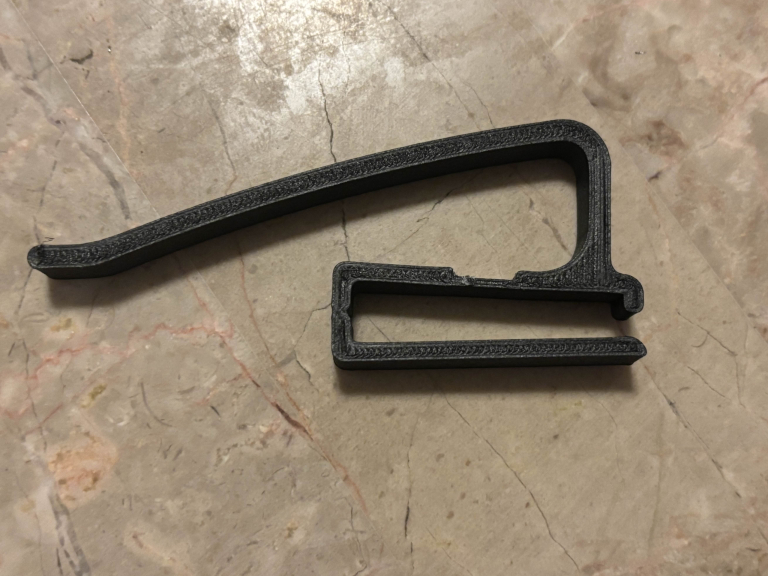
Initially the 50% Infill piece felt stronger compared to the Salt/Open-Air Annealing. Upon applying stress it was less prone to snapping. Unfortunately it still suffered separation between the walls and infill.
This is not good because this specific area needs to be able to withstand a high amount of constant stress and if it fails it could cause serious issues such as plastic falling off while driving and the whole bottom portion of the holder dropping down.
Another issue is the bend-zone I created, it would snap when trying to connect all parts together. I do not believe this would be an issue during average use as its not an intended movement that would ever be done. Since I don't believe this would be an important issue, I will not prioritize resolving it at this time.
90% Infill Water Annealing
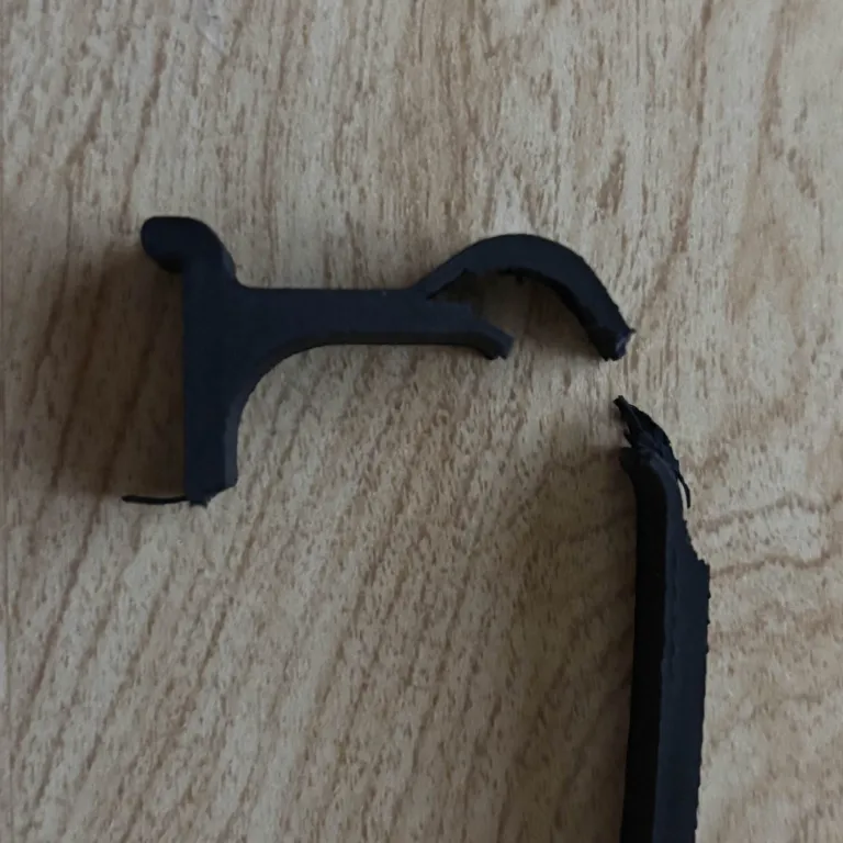
The 90% Infill piece was significantly heavier and sturdier. Active bending was harder and took more effort than the 50% infill.
As stress was applied, the part did not snap like the 50% infill did, it was able to withstand more stress without failure. This is the strongest iteration thus far and I believe it may be the infill I will use in the future. I will test lower amount of infill ranging from 55% to 85% to find the piece with the most strength.
New Updated Design
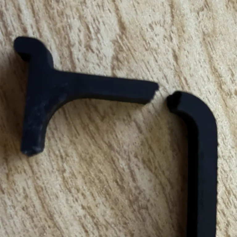
As I went through the process of testing the previous design, I met with my professor Luis Cabrales and got advice that I should try using something like metal for the part that connects to the visor.
This was recommended because metal has more memory and is not affected by temperature as much as plastic is. I thought this was a good idea I updated my design to be more efficient and contain a singular visor mounting area.